Check Your Leads
Before getting hold of Lanciatrek you need a working USB to Fiat 3-pin cable, see this video for how to test your cables so you know they work with your car. For more information and the complete Lanciatrek cable guide click here.
The integrale uses a proprietory 3-pin Fiat diagnostic connector, this was originally designed to connect to the Fiat FLT handheld tester. Modern engine management diagnostic systems utilise the OBDII standard which has a standard 16-pin connector which all modern car manufacturers use.
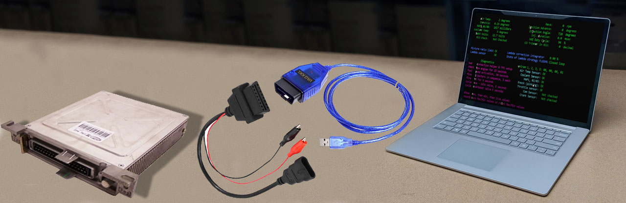
Fortunately for us cables are available which have the Fiat 3-pin connector one end, and an OBDII socket on the other, with a pair of crocodile clips for power. This will then connect directly to an OBDII to USB cable, which when combined allows us to connect the integrale's ECU to a modern computer running Lanciatrek. So we need:
integrale to FIAT 3pin / OBDII to OBDII / USB to Lanciatrek
Note that the 3-pin connector comes with a pair of flying leads that need to be connected to ground and power. This is because the integrale's ECU diagnostic socket does not provide external power unlike the OBDII standard which relies on power from the car. These wires power the interface within the leads.
SO YOU WILL NEED 2 CABLES AND A SMALL MODIFICATION TO THE FIAT END TO PROVIDE THE POWER.
Available from all the usual sources, eBay, Amazon etc. Search for 'Fiat Diagnostic Cable', they are approximately £10. Do not go for the cheapest option as I have found that some don't have very good contact surfaces and even once plugged in have intermittent connections (if any!). Another thing to be careful of is that some of the cables have an incorrect 3-pin plug on them which does not fit the integrale's socket. The correct connectors have a centralised, evenly spaced set of pins with a plastic insulator between two pins. Some connectors also have flat, blade pins which again, do not fit the integrale's socket.
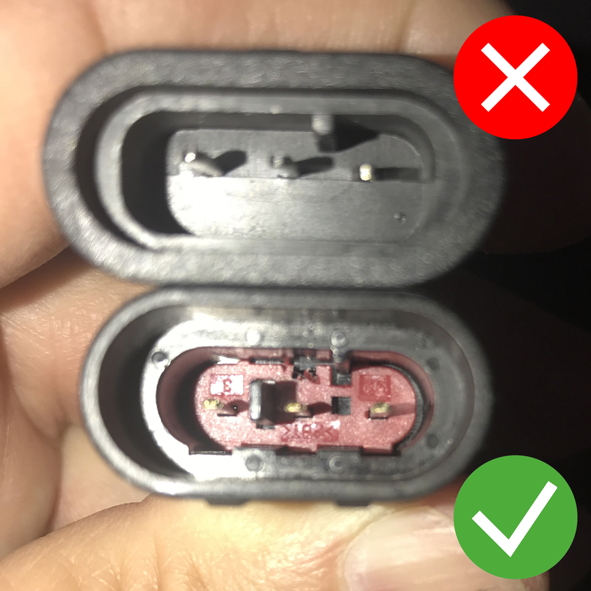
The top connector has its pins in the upper 3rd of the surround, the lower (correct) connector has its pins along the centre line. Also notice the black plastic key between the pins.
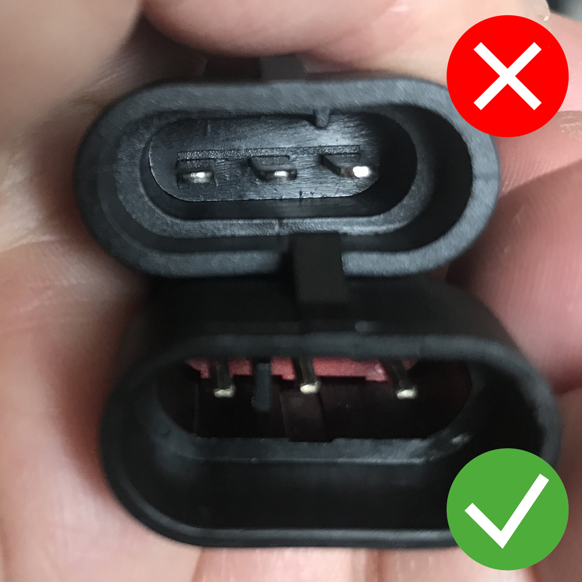
The upper connector has wide spade pins, the lower (correct) connector has narrower pins. Notice the plastic key within the lower connectors.
To power the interface via the crocodile clips I recommend connecting a cut off USB charging cable to them. This enables it to be powered by a computers standard USB socket (they provide 5v at 500mA and the cable only needs approx. 20mA). Some leads I had that didn’t work started working when powered from a USB.
INCORRECTLY CONNECTING THE (UNFUSED) POWER WIRES MAY CAUSE ECU DAMAGE.
Powering the leads via USB is much easier and tidier to work with compared to connecting the crocodile clips to another power supply. Also, before I began using a USB power source, once in a blue moon the car would not start whilst the diagnostic connector was attached to the ECU but just lying under the carpet. Since I switched to USB power, I have not had this problem, hence USB power is the tried and tested recommended path to follow.
USB connectors have 4pins / wires. The inner two pins are the data lines, optionally these can be shorted together as this tells your computer that the cable is a dumb power cable and not a USB data link. The outer two pins normally have a red (5v) and black (GND) wire. These need to be soldered onto the corresponding crocodile clip wires. Red to Red, Black to Black.
DOUBLE CHECK THE POLARITY OF THESE CABLES BEFORE CONNECTING THEM TO THE CAR. ITS YOUR SOLE RESPONSIBILITY TO ENSURE YOU HAVE WIRED THE CONNECTOR CORRECTLY. DONT ASSUME THE WIRES ARE RED AND BLACK, TEST THEM SO YOU KNOW. I WILL NOT BE RESPONSIBLE FOR ANY DAMAGE YOU CAUSE BY FOLLOWING THE ABOVE. IF YOU DO NOT ACCEPT THIS THEN PLEASE DO NOT ATTEMPT TO MAKE A CABLE.
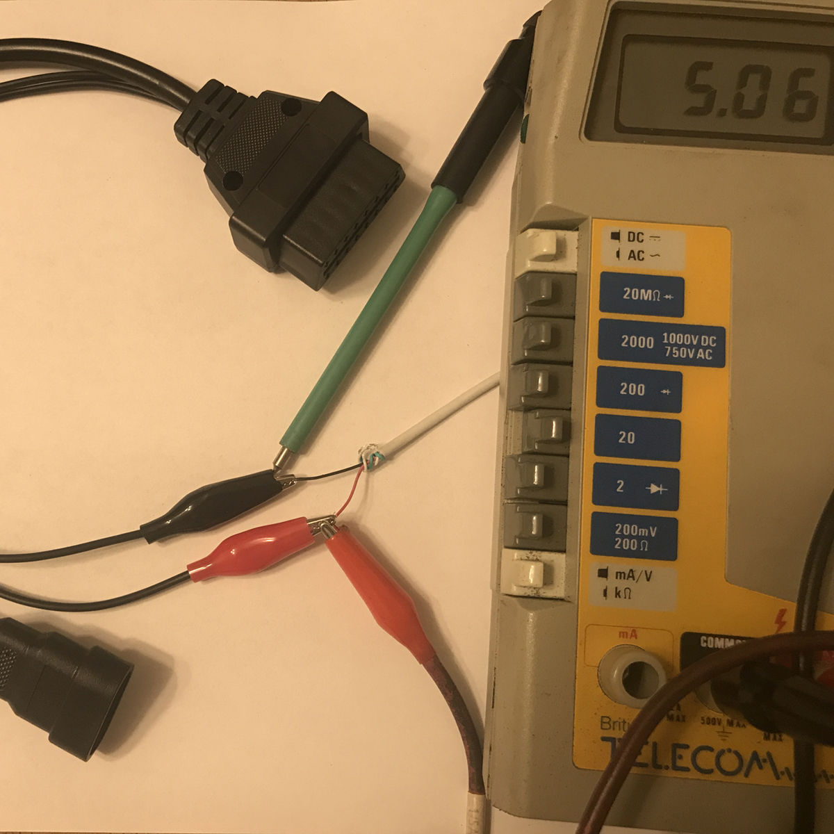
Attach a multimeter to the red and black crocodile clips, you should see +5v DC if you have wired the USB power cable correctly, assuming you have inserted the other end of the cable into a powered USB socket.
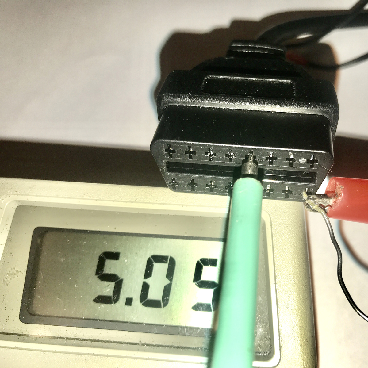
Here I am also testing the power on the OBDII socket. The green probe is the signal ground pin and the red clip is on the power pin. Again you should see +5v DC, if all is well.
This is the simple one available from the usual sources eBay / Amazon etc, search for 'OBDII USB KKL' ideally a 409.1 KKL lead (again typically £10). VAG-COM leads are often suitable, they are normally plug'n'play but if they do not work they can normally be modified to work.
If it doesn't work and the 2 long pins on the OBDII plug are not connected together (test them with a meter), then take the covers off and solder a wire between them so they are shorted together. On VAG vehicles these are assigned as Pin 4 Chassis Ground and Pin 5 Signal Ground and are separate. But our cars only have one earth, by joining them you are guaranteeing there is a good earth available for the cars data connection.
Previosuly there was an issue with some USB chipsets used within the OBDII cables, however all the programs are now coded to work with both the FTDI and the CH340 chipsets which are the most common ones found in these cables.
AS A FINAL PRECAUTION BEFORE CONNECTING THE CABLES TO THE ECU OR YOUR LAPTOP, CHECK THE POWER POLARITIES ARE CORRECT WITH REFERENCE TO ODB WIRING DIAGRAMS AVAILABLE ONLINE AND THE FIAT 3-pin CONNECTOR AS PER THE INTEGRALE WORKSHOP MANUAL.
You should end up with a cable that has a 3pin Fiat connector one end, and a pair of standard USB connectors the other end, with a lump in the middle containing the OBDII plug and socket. The 3pin goes into the integrales ECU diagnostic socket found in the centre console within the footwell and the USB connectors go into your computer (laptop) to provide the data and power connections.
Once I have confirmed the cables are connected to provide the correct polarity I solder the power wires permanently in place, covering them with shrink wrap. See the image below.
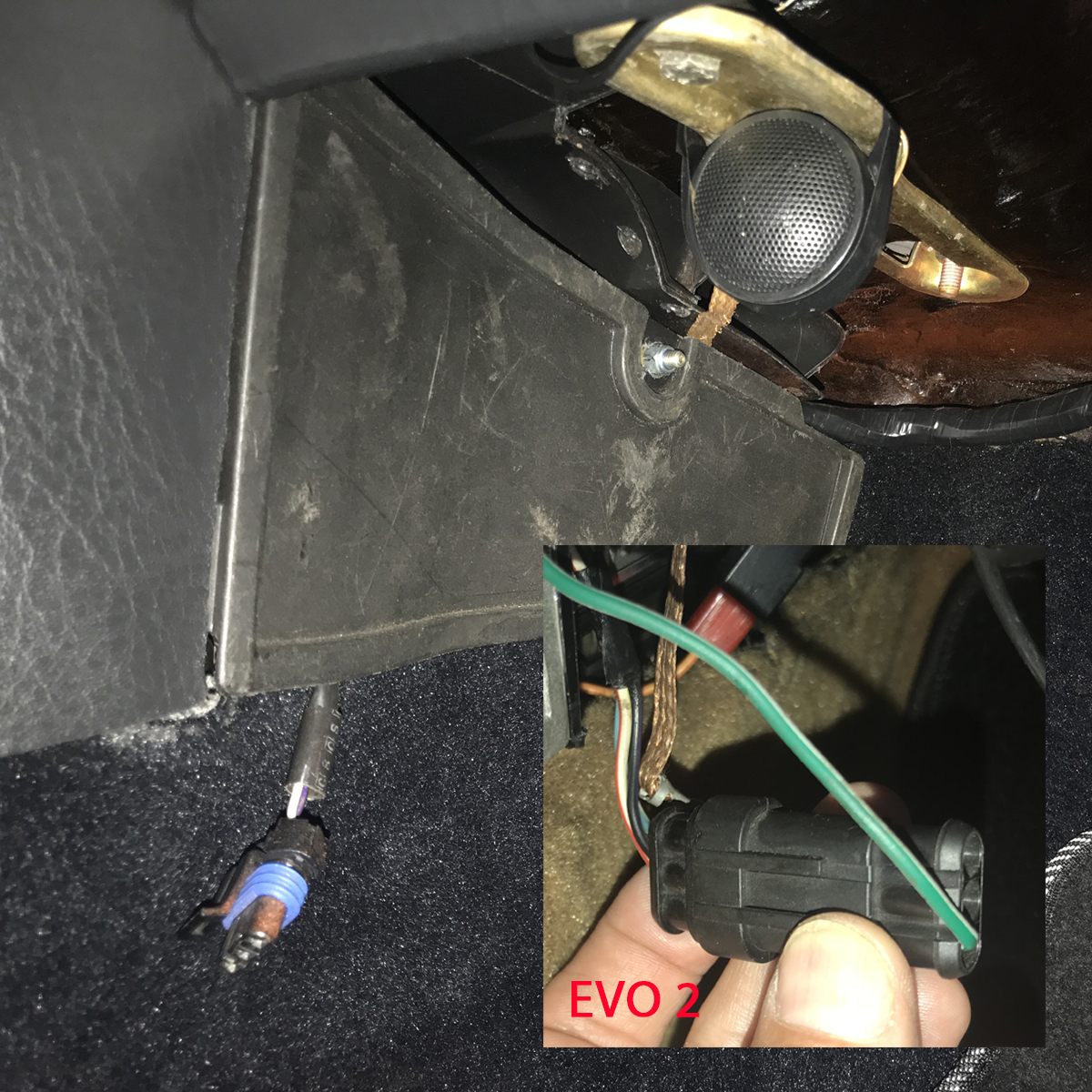
The ECU is located within the footwell, in the centre column behind an access panel which normally has a knurled plastic nut holding it on, mine has a hex nut in this photo. Notice the dangling diagnostic connector. The inset image shows the Evo 2 connector, unclick the plug and seperate to access the diagnostic connector (see below).
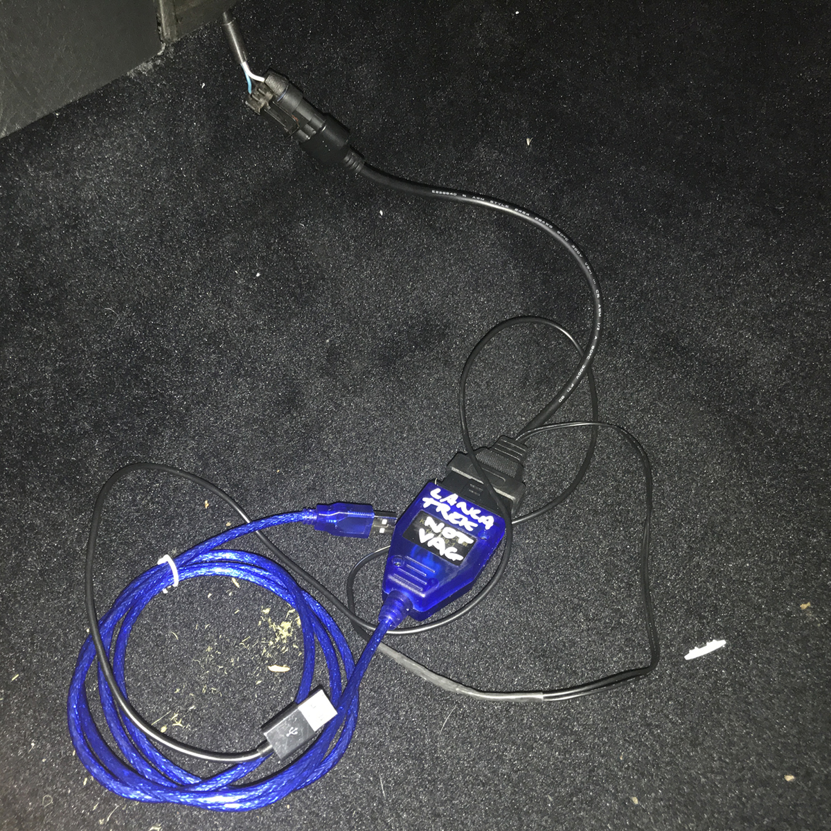
The final cable, connected to the diagnostic socket. Notice the two USB connectors, the blue cable is the data connection, the black cable is the 5v power (I used an old phone charger cable). For ease of access I leave the cable connected and coil it under the carpet when not in use.
Evo 2 Users: The Evo 2 diagnostic connector is normally attached to the warning light within the dashboard via the green and white wire in the above image. Hence to connect your diagnostic cable to the Evo 2, you need to simply unclip and part the connectors shown above. Once you have finished, re-connect the green/white wire. If you leave the diagnostic cable connected on an Evo 2 you will disable the ECUs ability to switch the dash warning lamp on/off.
Note: If the engine will not start when you switch the ignition on simply disconnect and re-connect the Fiat 3pin plug, or the OBDII connector.
Once you have a functional cable, its handy to test it to make sure it will work with LanciatrekLite and Lanciatrek. To that end I have produced a simple lead testing app which is linked below, if you scroll down there is also a link to my YouTube video which shows the Lead Tester App in operation.
Before getting hold of Lanciatrek you need a working USB to Fiat 3-pin cable, see this video for how to test your cables so you know they work with your car. For more information and the complete Lanciatrek cable guide click here.
Just a quick video done in my garage late one night to briefly show you. A better one should appear in the future, showing more. Reads a Lancia Delta Integrale ECU WH4 type, recognised and displays the ECU code and vehicle model as well as setting up the screen for that model.
The software should now read the ECUs of ALL Delta Integrale ECUs and identify which one you have. All you need is a Fiat 3-pin to OBDII lead (I power mine from a USB port using an old chopped up USB charging lead).
The free version 'LanciatrekLite' (formally known as lanciatrekdos) runs from a Windows Command Prompt, this video shows you how. All you need is a Fiat 3-pin to OBDII lead (I power mine from a USB port using an old chopped up USB charging lead).
"These tools have been created by an enthusiast for enthusiasts to help them keep their iconic cars running. I don't want to sell these for hundreds of pounds as that defeats the object of me helping, however if you find this useful please consider donating via PayPal using the button above. Donations will allow me to develop it more and also send you a personalised copy of my latest fully featured integrale ECU reader."
coxeey
May 2020
LanciatrekLite free engine diagnostic software for the Lancia Delta HF integrale (includes HF4WD but EXCLUDES the Evo2).
Lanciatrek (formally trekWin) the fully featured diagnostic tool, all the bells and whistles to help you maintain your Lancia Delta HF integrale (all models including Evo2 and all Special Editions) also includes the HF4WD.
You will also need a pair of cables, see here for precisely what is required.
The full version of Lanciatrek (formally trekWin) is my fully functional Lancia Delta integrale ECU Reader and Logging Tool. This version is fully featured and is only available direct from me (coxeey) to those who donate towards this project. Contact me for more details.